Table of Contents
LEGO Chase Demo
This page describes how to make a LEGO robot that chases things, like a ball. It's the same robot and program that's used in the Pixy LEGO video. This robot and program is a good launching point for other projects, and it's a good introduction to PID control, which is used throughout robotics and engineering in general.
Building the robot
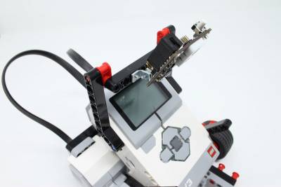
The robot we're going to build can be found in Laurens Valk's book LEGO Mindstorms EV3 Discovery Book. The robot is called the Explor3r and it uses parts that are available in the retail Mindstorms EV3 kit.
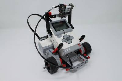
- Assemble Explor3r through step 11. Click here for instructions on how to build Explor3r.“ That is, stop short of mounting the IR Sensor (step 12). Instead of the IR Sensor, we'll be mounting Pixy2.
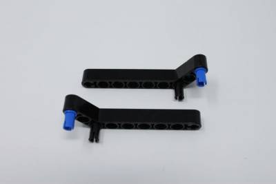
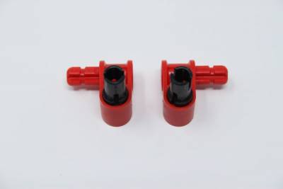
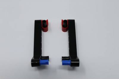
- Locate these LEGO parts and your LEGO-mounted Pixy2. (There are instructions on how to mount Pixy2 to LEGO here)
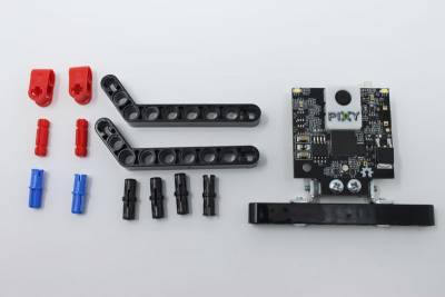
Cables (IMPORTANT!)
- The motors connect to motor ports A and B on your brick. Don't “cross” the cables. That is, if you are facing the motor ports (the back of the robot), the left motor connects to port B, the right motor connects to port A.
- Pixy2 connects to sensor port 1.
Teach Pixy2 an object
Go ahead and teach Pixy2 an object. You might try using the button press method. Using the button press method doesn't require that you hook up a USB cable to Pixy2 and run PixyMon, so it's much more convenient!
Load Chase Example
- Turn on your LEGO brick if you haven't done so, and hook up a USB cable between your computer and your LEGO brick.
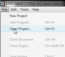
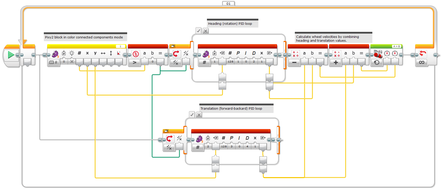
- Browse to the location where you unzipped the “LEGO blocks and examples” file (which you can download on this page), and then to the examples directory and select “ccc_chase.ev3” and click on Open. You should see a program that looks like this (below).
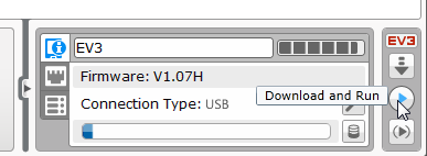
- To run the chase program:
- Make sure you have a fair amount of space for your robot to move around in.
- Make sure Pixy2 can reliably detect/track your object. (Look at Pixy2's LED. Does it glow when the object is present?)
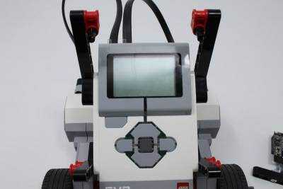
- Tilt Pixy2's lens down such that it is looking slightly down at the ground, like in the final assembled picture above.
- Place the object that you taught Pixy2 on the ground in front of the robot, but such that Pixy2 can still see it. (A ball is perfect for this.)
You should notice that the robot chases the object. Or more specifically, it will maintain a certain distance from the object. If the object is farther away, the robot will approach (chase) the object. If the object is too close, the robot will back up until the correct distance to the object is reestablished.
Troubleshooting
If your robot doesn't chase after your object, here are the things to check first.
- Check to make sure that Pixy2 can track your object reliably. Bring up PixyMon to verify. If it doesn't track the object reliably, this page has some helpful pointers.
- If your robot turns away from your object, make sure that the motor cables aren't crossed. That is, if you are facing the motor ports (the back of the robot), the left motor connects to port B, the right motor connects to port A.
- If your robot gets too close to your object when it's chasing it, tilt Pixy2 such that it is looking more level. Alternatively, if your robot isn't getting close enough to your object while it's chasing it, tilt Pixy2 more down.
- Sometimes it's easier to debug things with the robot “up on blocks” such that it can't move, but its wheels are free to rotate.
What's going on in the chase program?
The track program uses X centroid output of the Pixy block

to adjust the heading of the robot by using a PID controller.

That is, the X centroid output of the Pixy2 block ranges between 0 and 255, depending on where the detected object is in Pixy2's image. The “center pixel” is therefore 128. The PID controller tries to move the motors such that the detected object is always centered in the image. It does this by comparing the X centroid value to 128 (the PID controller's Set Point input).
The Control Output of the PID controller is fed directly into the left wheel controller (the Power Left input of the Move Tank controller block). The Power Right input is fed the inverted output of the PID controller by subtracting the PID controller's output from 0. Why are the wheels controlled in opposite directions? We are interested in controlling only the rotation of the robot, and rotating the robot is achieved by powering the motors in opposite directions at the same power/speed. It is in this way that the robot “tracks” the object and always faces it.
There is some additional logic in the program to make sure that if there are no detected objects, the robot doesn't move. This is done by comparing the Signature Output of the Pixy2 block with 0. If the Signature Output is zero, Pixy2 has not detected an object. If the Signature Output is non-zero, Pixy2 has detected an object. The Switch block selects between these two possibilities and feeds the PID controller output into the motors when an object is detected, and feeds 0 into the motors when no objects are detected.
Some notes on adjusting the PID gains
The appeal of the PID controller is it's flexibility. By adjusting the three gain values, one for proportional, one for integral, and one for derivative, lots of different systems can be controlled. So what's up with the PID values? How were they chosen?

These were “tuned” by experimentation. You can tune the PID loop yourself. In fact, it's a good way to familiarize yourself with PID control.
Go ahead and set all of the PID gains to 0. That is, click on Proportional input of the PID block and set the value to 0. Do the same for the Integral and Derivative inputs. Now all of the PID gains are 0. You can try to run the program now. And if you guessed that your robot won't move, you're correct!
The proportional gain “does most of the work” as they say, so tuning should begin by adjusting this value. Start with a small value of 0.1 and run the program. Notice how the robot is now very slow and sluggish. That is, when trying to track the object (which you're moving around) the robot seems to be trying, but it's heart doesn't seem to be into it. This is telling you that your proportional gain is too small.
Try setting the proportional gain to 1.5 and run the program. You might notice that the robot does a shimmy after it faces your object. In other words you move the object quickly, and the robot responds by turning to face the object, and instead of stopping when it faces your object, it keeps on going. It overshoots. In fact, it may overshoot several times before coming to a rest, finally facing your object like it was programmed to do. This is oscillation, and it's a very common problem.
To reduce the oscillation, you need to increase the derivative gain. Increasing the derivative gain is like adding friction to your system, which may sound like something you should avoid. However, increasing the derivative gain does not adversely affect the efficiency of your system as friction does. Start by setting the derivative gain to the same value as the proportional gain. And continue to increase the derivative gain until the oscillation is under control.
However, if increasing the derivative gain does not remove the oscillation, the proportional gain may be too high. Try reducing the proportional gain (cutting it in half, say), then setting the derivative gain to zero again, and starting over by increasing the derivative gain until the oscillation is removed.
If you're successful in removing the oscillation, you might try your luck by increasing the proportional gain again (not as high as before) and seeing if you can still bring the oscillation under control with derivative gain. And if you're unsuccessful in removing the oscillation, you can always reduce the proportional gain and try different derivative gains as before.
Our goal is to have our robot that tracks the object quickly but without oscillation. This is usually the goal, but you may want a robot that oscillates or is sluggish. It's all up to you!
What about the integral gain? Integral gain is useful when the system has trouble reaching the goal. Say if our robot tended to get close to facing our object and then stopped, we could try adding a little integral gain. The integral gain would then make sure that the robot would face the object, eventually. The integral gain is zero in this example because the LEGO motors have their own built-in control loops that make sure that we always reach our goal.
Chasing the object
What's going on in the chase program?
If you read and understood the section on how the track program works, much of the chase program should make sense. The main difference is the extra PID controller. The new controller takes the Y Centroid output of the Pixy2 block and compares it to 150. Why 150? The Y Centroid output varies between 0 and 199 depending on the position of the detected object in the image. If the object is higher in the image, the Y Centroid value is lower, and if the object is lower in the image, the Y Centroid value is higher. It's backward in a sense, but many cameras follow this same scheme.
Now consider that Pixy2 is angled slightly such that it is looking downward. This allows your robot to use a simple distance-measuring technique. Assuming the object of interest is resting on the ground if the object is higher in the image, it is farther away from Pixy2. If the object is lower in the image, it is closer to Pixy2. In fact, you can estimate the actual distance by performing a simple calculation: distance = constant * 1/(1 + Y Centroid). You just need to figure out the value of the constant by doing some simple calibration with a known distance. Anyway, by choosing the value of 150, we are choosing the lower part of the image, or when the object is relatively close. You can change this value if you like. In particular, if you lower the value (to 100, for example), the robot will stop when it is farther away. If you raise the value (no greater than 199 though!), the robot will stop when it is closer.
How is the output of the new PID controller used to control the motors? The track program was already controlling the motors such that it controlled the rotation of the robot. The new PID controller must somehow control the translation (forward/backward) motion of the robot while not interfering with the rotation motion. It does this by using a simple set of equations.
rotation = left_motor - right_motor
translation = left_motor + right_motor
If you've ever driven a tank, these equations probably make sense. But we're interested in the “inverted” equations. We want expressions for the left_wheel and the right_wheel in terms of rotation and translation. That is, we already know how we want our robot to rotate and translate – these are the outputs of our PID controllers. So rotation and translation are our knowns. Our unknowns are left_wheel and right_wheel. Using some algebra, we get the inverted equations.
right_motor = (translation - rotation)/2
left_motor = (rotation + translation)/2
If you look at the program, these equations are implemented in the math blocks that feed into the Move Tank block. The divide-by-two's are missing, but since these are just multiplicative constants (ie multiply by one-half), they end up being taken up in the PID gain values when the gain values are chosen (tuned). (How convenient!)
Some notes on the PID block
By putting the PID controller in a block, we make things simpler. It's now very easy to make programs with PID control loops. In fact, you can use the PID block for other programs that don't use Pixy2. Use the PID block to control your robot's distance to the wall for a wall-following robot. That is, use the IR sensor (in proximity mode) as an input to the PID controller. And feed the output of the PID controller into the steering control of your robot.
But by making the PID controller a block, we hide the implementation details. These details are simple though and can be summarized with a few simple expressions.
error = Value_In - Set_Point
d_error = error - previous_error                                             // Simple derivative of error
i_error = i_error + error                                                    // Simple integral of error
previous_error = error                                                       // Remember the error from the previous control cycle
Control_Output = Proportional*error + Integral*i_error + Derivative*d_error  // This is "belly of the beast".  Not much of a beast though... :)
Using these expressions as a guide, you can try creating your own PID block in the LEGO EV3 programming environment.
Where to go from here
You've created a robot that can chase things. Using the same concepts you can create a robot that goes over to an object and picks it up. Or you can create a robot that launches projectiles at things. Or you can create a robot that goes over to its charger and plugs itself in. Or you can create the worlds first (as far as we know) soccer-playing LEGO robot. The programs to create these robots are more complicated but armed with these concepts, much of the added complexity is in the interleaving of these concepts.
So think about what you want your robot to do, then do it! (And by all means, tell us about it! support@pixycam.com)
