Table of Contents
Assembling the pan/tilt Mechanism
When combined with Pixy, the pan/tilt mechanism makes a fun demo — a good “hello world” for Pixy (no Arduino required). The pan/tilt mechanism comes in a kit and requires some assembly.
Note: the servos in the pictures will look different than the ones in your kit. They are functionally identical, so please don't worry!
Pixy Modification
For these servos to work properly, you will need to make a small modification to Pixy. Unfortunately, it requires a soldering iron and a bit of solder, but the modification is easy and doesn't require much soldering skill.
The new servos are more efficient and require less power (which is good), but they are more sensitive to voltage drops. The current-limiting resistors (the big ones R18, R20) need to be bypassed. If they are not bypassed, the pan/tilt motion may be erratic (which is bad).
Locate C25 and C26 on the back side of Pixy toward the right edge of the board. We need to short the two inner pads of C25 and C26:
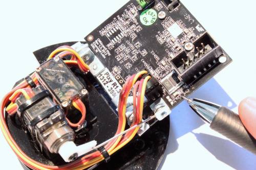
Do this by placing your soldering iron and heating up the two inner pads of C25 and C26 while adding solder. The solder should easily bridge once enough solder has been added:
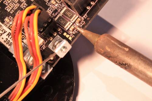
The complete modification looks like this:
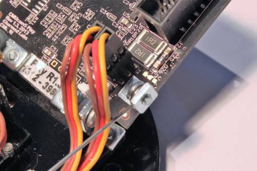
OK, once that's done, you're ready for the…
Pan/Tilt Assembly
You will need the following (in addition to a Pixy and a pan/tilt kit):
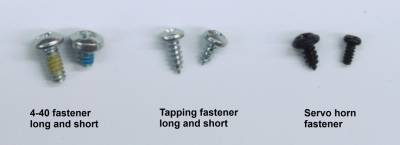
Fastener Types
There are lots of different types of fasteners included in this kit. Refer to the picture below to help you find which fastener we are referring to in these instructions.
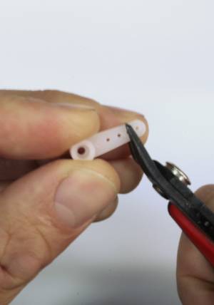
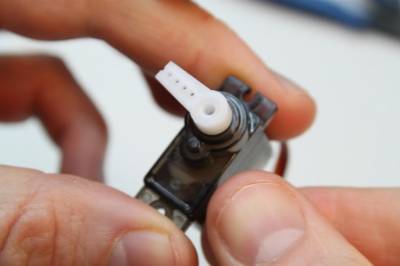
1 - Find one of the long servo horns inside one of the servo baggies, and clip it on the 2nd hole from the end.
You might notice that the later photos show the servo horn with 4.5 holes. Don't freak out - when properly clipped, your horn should have 2.5 holes, like in this photo:
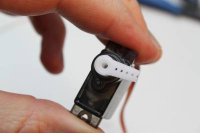
2 - Put the servo horn on the servo and check both ends of travel. You can do this by moving the horn all the way to the right:
and then all the way to the left:
and adjusting the mounting angle of the horn such that the center of travel has the servo horn pointing downwards. Note, it's OK to move the servo in this way even though it requires a fair amount of force. And it makes a cool sound!
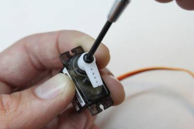
3 - Find one of the servo horn fasteners in the one of the servo baggies. (Refer to the fastener picture above.) Screw the servo horn tightly. (In the picture below, the servo is shown with the servo horn pointing downwards, which should be roughly the center of travel.)
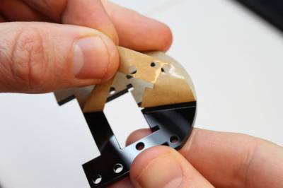
4 - Remove the paper backing on the pan/tilt body (the smaller of the two acrylic parts).
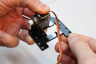
5 - Fit one of the servo mounting tab into the slot on the pan/tilt body.
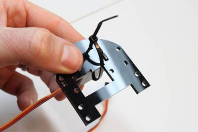
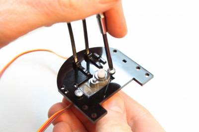
6 - Flip the body over and thread a cable tie through the cable tie slots in the body.
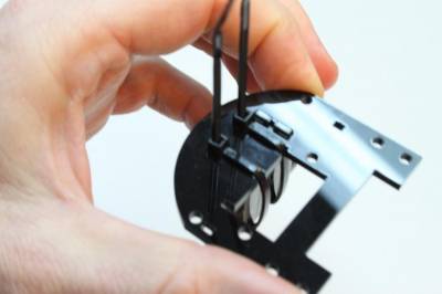
7 - Thread another cable tie through the other cable tie slots in the body.
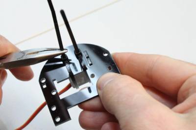
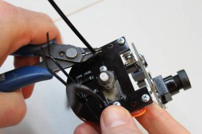
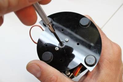
8 - Tighten both cable ties by using pliers. It requires quite a bit of force to fully tighten!
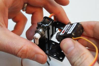
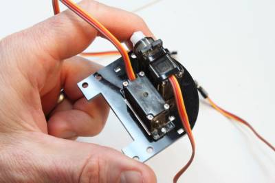
9 - Take the 2nd servo and place in the other hole in the body as shown in the picture. Note that the wires for the servos are pointing in opposite directions.
10 - Grab two of the long tapping fasteners. (Refer to the fastener picture above.) Use these fasteners to secure the 2nd servo.
(make sure not to overtighten! Snug is fine)
11 - Take all five right-angle brackets out and examine them. Notice that three of them have two threaded holes and two of them have one threaded hole. We'll call these two-threaded and one-threaded brackets, respectively. Go ahead and separate these two bracket types to make things easier.
Grab a two-threaded bracket. If you look really closely, you'll notice that one of its legs is ever-so-slightly longer than the other. Say what? It's true— I don't know why. But you can best see this by looking at the holes in the bracket. One of the holes in centered in its leg and the other hole is not centered, because its leg is slightly longer. Weird.
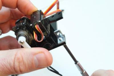
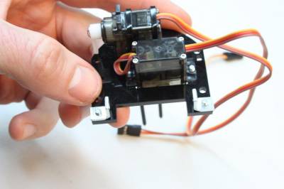
Take two long 4-40 fasteners and attach two two-threaded brackets to the body as shown in the pictures below. Attach them such that the short legs are touching the body and the long legs are pointing up.
Nice. Now put this assembly aside for now.
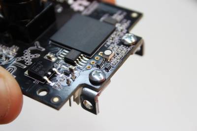
12 - Take your Pixy and attach two one-threaded brackets to it as shown in the picture below. Use two short 4-40 fasteners to do this. (Refer to the fastener picture above.)
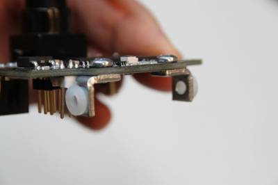
13 - Take two nylon bushings and press them into the non-threaded holes in these brackets.
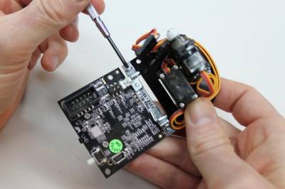
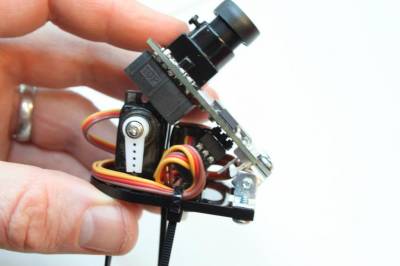
14 - Slide the Pixy into the body assembly. Use two long 4-40 fasteners and insert them from the outside as shown in the picture. The 4-40 fasteners will form an axle for Pixy to use for tilting. Make sure that the brackets are mounted squarely— this can cause binding. Tilt Pixy back and forth a couple times and make some adjustments if you feel some binding.
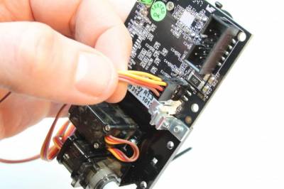
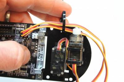
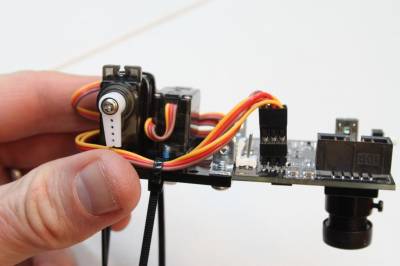
15 - Plug in the servo wires into the servo connector on Pixy. (The servo connector is the little 6-pin connector labeled J3.) The pan axis goes on the left and the tilt axis goes on the right, and the yellow wires on both connectors face up. (Which is the tilt axis? It's the one with the servo horn.)
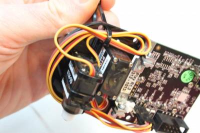
16 - Use a cable tie to secure the wires to the body as shown. String the cable tie through the single slot in the body and around the outside. Do not tighten the cable tie fully yet.
17 - Use the slots on the other side of the body to thread another cable tie and secure the wires on the other side as shown. The wires are longer than they need to be, so it requires some artistic arranging. Do not tighten this cable tie fully either.
18 - Verify that there is enough slack in the cables to allow Pixy to tilt fully forward and backward.
19 - When you're happy with the cable situation, make the ties snug, but not too tight (to save the wires) then flip over the assembly and clip the ends of the cable ties.
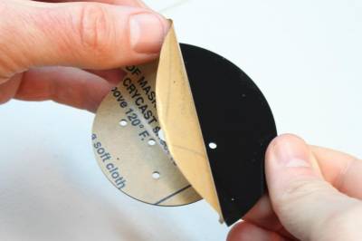
20 - Remove the paper backing from both sides of the pan/tilt base.
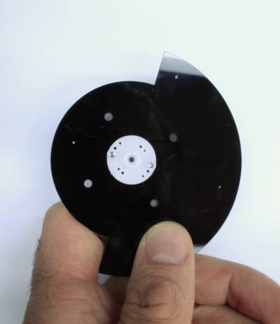
21 - Grab a circular servo horn from one of the servo baggies and attach it to the pan/tilt base with two short tapping fasteners. (Refer to the fastener picture above.)
It's a bit hard to tell from the photos below, but the shoulder (sticky-outy-bit) of the servo horn should be facing away from the pan/tilt base - not going through the center hole of the base. The servo horn has lots of holes – rotate it until some of the larger ones line up with the holes in the pan/tilt base, then screw it in place.
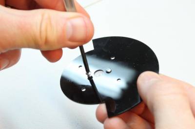
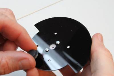
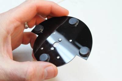
22 - Attach rubber feet to the bottom of the base as shown. There are little holes in the pan/tilt base that are there to help you position the rubber feet.
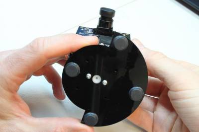
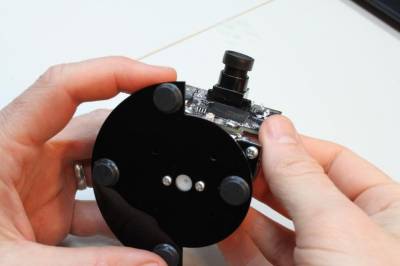
23 - Place the body assembly on the base assembly by attaching the horn to the pan servo. (The pan servo is the servo without the servo horn sticking out of the bottom.) Attach the servo horn such that the center of travel has the wide part of the base facing forward (where the camera lens is pointing). You can do this by moving the horn all the way to the right:
and then all the way to the left:
24 - Find one of the servo horn fasteners in one of the servo baggies and attach the base to the body. (Here, the wide part of the base is facing forward, which should be close to the center of travel.)
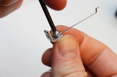
25 - Place a short 4-40 fastener through the eyelet of the wire pushrod and attach it to a two-threaded bracket, but don't tighten fully. The pushrod needs to be able to pivot around the screw. Attach the pushrod and fastener to the longer leg of the bracket.
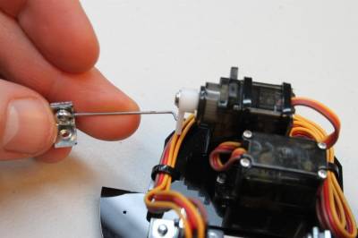
26 - Thread the pushrod into the bottom hole of the tilt servo horn. You need to insert the pushrod past the first bend, so that the section between the bends is in the servo horn hole.
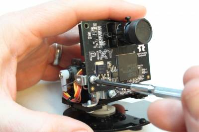
27 - Attach the bracket to Pixy with a short 4-40 fastener.
You're done!
What's next? Run the pan/tilt demo!
